Template Community
/3-way Wiring Diagram
3-way Wiring Diagram
Share
Duplicate

2
0
Report
Publish time:12-16-2021
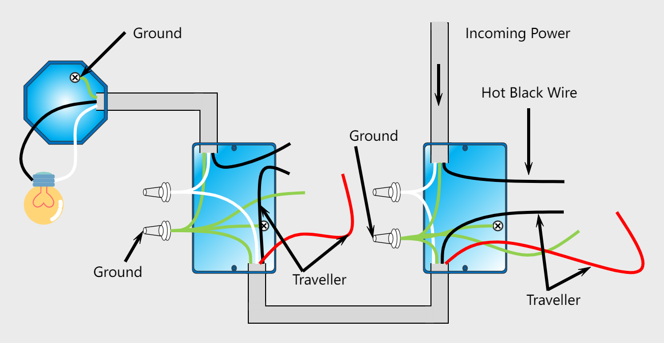
In this case, the wires from the power source go from one switch to another, then the fixture. The white wire connected through the wire nuts moves uninterruptedly from the source to the light fixture. The hot black wire is connected to the common terminal of the first switch, and then it is carried by paired travelers to traveler terminals in the second switch. Lastly, the common terminal of the second switch sends the black wire into the light fixture. In building wiring, multiway switching is the interconnection of two or more electrical switches to control an electrical load from more than one location. A common application is in lighting, where it allows the control of lamps from multiple locations, for example, in a hallway, stairwell, or large room. In contrast to a simple light switch, a single-pole, single-throw (SPST) switch, multiway switching uses buttons with one or more additional contacts, and two or more wires are run between the switches. When the load is controlled from only two points, single-pole, double-throw (SPDT) switches are used. Double pole, double throw (DPDT) switches allow control from three or more locations. In alternative designs, low-voltage relay or electronic controls can switch electrical loads, sometimes without the extra power wires.
Creator
Ashley
Follow

Post
Recommended乐动体育不提款